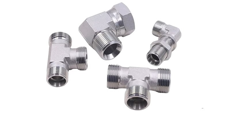
In fluid piping systems, connectors and ports have many applications. Before adding or replacing them on a tube or hose, you need to correctly identify them in your specific application.
Thread characteristics have many types, such as pitch, angle, diameter, and form. To classify them, manufacturers use identifiers such as ASME B1 .1 and ISO 261.
There are many the International Organization for Thread Standardization: SAE International, British Association, and Deutsches Institut für Normung, and the American Society of Manufacturing Engineers, American National Standards Institute.
| Combustible cónico de National Pipe | NPTF |
| National Pipe Straight Mechanical | NPSM |
| International Standards Organization | ISO |
| Sociedad de Ingenieros Automotrices | SAE |
| Joint Industrial Council | JIC |
| Asociación Nacional de Energía Fluida | Asociación Nacional de Protección Ambiental |
| Tubería estándar británica | BSP |
| Deutsche Industrial Norme | ESTRUENDO |
| Norma industrial japonesa | JIS |
| Tubería cónica estándar británica | Licenciado en Ciencias Políticas |
| Tubería paralela estándar británica | BSPP |
Fluid port and connector identification tools
When measuring inner and outer diameters of threads, you could use calipers.
Measure the amount of threads per inch and the thread-to-thread spacing in metric applications, always used thread pitch gauge.
American Connections - mechanical connection
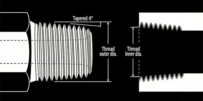
NPTF - National Pipe Tapered Fuel
The abbreviation for National (American) Pipe Thread refers to a 60-degree tapered pipe thread used in North America, particularly advantageous for fuel transportation. This threaded connection can be used for both external and internal thread fittings. Its external thread is compatible with NPTF, NPSF, or NPSM internal threads. It's important to note that NPTF and BSPT fittings, while similar, are not interchangeable due to differences in their pitch and thread angle. The male and female threads connect, and a seal is formed when they are mated together (i.e., threads deformation). This is known as a dry seal thread. It provides a high level of sealing without the need for fillers or sealants. While the National Fluid Power Association (NFPA) does not recommend this connection for hydraulic applications, it is commonly found in fluid piping systems, such as in aerospace and chemical industries where high sealing performance is crucial for liquid pipeline transportation.
| Inch size | Tamaño del guión | Threads per Inch | Male Thread O.D. (in) | Female thread O.D (in) | ||
| 1⁄8 | -2 | 27 | 13⁄32 | 0.41 | 3⁄8 | 0.38 |
| 1⁄4 | -4 | 18 | 17⁄32 | 0.54 | 1⁄2 | 0.49 |
| 3⁄8 | -6 | 18 | 11⁄16 | 0.68 | 5⁄8 | 0.63 |
| 1⁄2 | -8 | 14 | 27⁄32 | 0.84 | 25⁄32 | 0.77 |
| 3⁄4 | -12 | 14 | 1 1⁄16 | 1.05 | 1 | 0.98 |
| 1 | -16 | 11 1⁄2 | 1 5⁄16 | 1.32 | 1 1⁄4 | 1.24 |
| 1 1⁄4 | -20 | 11 1⁄2 | 1 21⁄32 | 1.66 | 1 19⁄32 | 1.58 |
| 1 1⁄2 | -24 | 11 1⁄2 | 1 29⁄32 | 1.9 | 1 13⁄16 | 1.82 |
| 2 | -32 | 11 1⁄2 | 2 3⁄8 | 2.38 | 2 5⁄16 | 2.3 |
National Pipe Straight Mechanical (NPSM)
NPSM stands for "American Standard Straight Pipe Thread for Mechanical Connections," belonging to the non-sealing pipe thread family. Both male and female NSPM connectors have straight threads with a 60-degree thread angle, requiring a sealing gasket. This type of thread achieves a reliable connection without sealant. An NPSM mechanical connection is made when both male and female threads are mated together. It is commonly found in hydraulic systems and low-pressure pipelines. It is frequently used in valve and pipe transition connections or for quick assembly/disassembly between equipment, such as in factory hydraulic systems or laboratory instrument interfaces. The standard designation for NPSM threads is ANSI B1.20.1. According to ASME B1.20.1, NPSM thread specifications are indicated in the format of "nominal size threads per inch." For example, "1/2-14NPSM" indicates a nominal diameter of 1/2 inch and 14 threads per inch. The tapered seat creates a leak-resistant connection and is commonly found in fluid power systems.
| Inch size | Tamaño del guión | Threads per Inch | Male Thread O.D. (in) | Female thread O.D (in) | ||
| 1⁄8 | -2 | 27 | 13⁄32 | 0.41 | 3⁄8 | 0.38 |
| 1⁄4 | -4 | 18 | 17⁄32 | 0.54 | 1⁄2 | 0.49 |
| 3⁄8 | -6 | 14 | 11⁄16 | 0.68 | 5⁄8 | 0.63 |
| 1⁄2 | -8 | 14 | 27⁄32 | 0.84 | 25⁄32 | 0.77 |
| 3⁄4 | -12 | 14 | 1 1⁄16 | 1.05 | 1 | 0.98 |
| 1 | -16 | 11 1⁄2 | 1 5⁄16 | 1.32 | 1 1⁄4 | 1.24 |
| 1 1⁄4 | -20 | 11 1⁄2 | 1 21⁄32 | 1.66 | 1 19⁄32 | 1.58 |
| 1 1⁄2 | -24 | 11 1⁄2 | 1 29⁄32 | 1.9 | 1 13⁄16 | 1.82 |
| 2 | -32 | 11 1⁄2 | 2 3⁄8 | 2.38 | 2 5⁄16 | 2.3 |
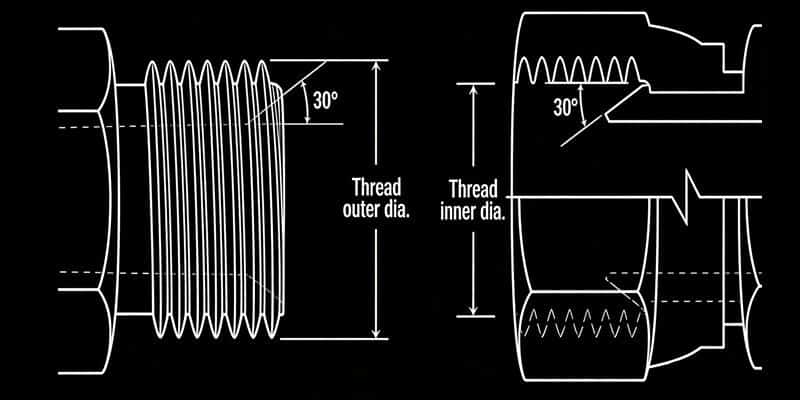
Abocardado JIC 37° (SAE J514)
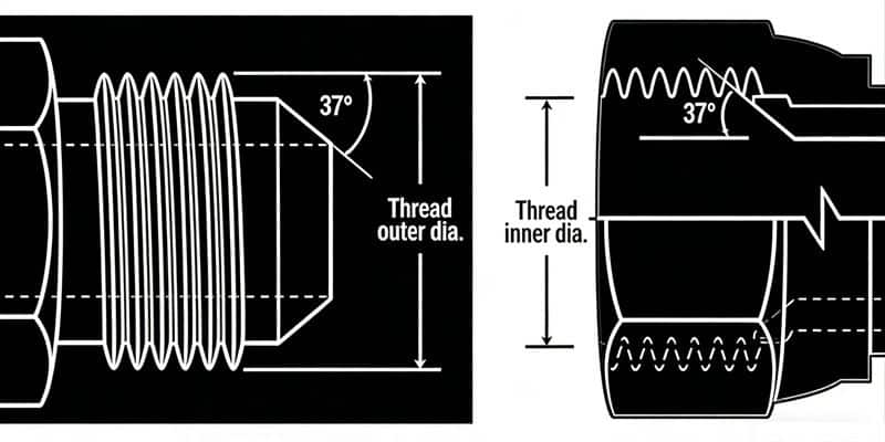
JIC 37° is based on the SAE standard. "JIC" indicates that the fitting conforms to the standards set by the Joint Industry Conference, and "37°" indicates that the sealing face angle of the fitting is 37 degrees. This type of threaded fitting is widely found in hydraulic systems to ensure a good seal. Both the JIC male and JIC female of this connection have a 37° flare seat, which is the high-pressure hydraulic line standard specified by the Society of Automotive Engineers (SAE). Its 37° cone angle or cone seat design is specifically designed for this application. This type of fitting is commonly referred to as a JIC fitting. It is worth noting that the JIC external thread is a straight thread and can only be matched with the JIC internal thread, and both have a 37° cone seat. This design allows the seal to be effectively formed at the 37° cone seat. The straight threads of each half hold the connection together mechanically. However, while most SAE J514 threads look identical to SAE 45º flare threads, their seating angles do not match. You need to carefully measure the cone angles to make an accurate distinction.
| Inch size | Tamaño del guión | Tamaño de la rosca | Male Thread O.D. (in) | Female thread O.D (in) | ||
| 1⁄8 | -2 | 5⁄16 - 24 | 5⁄16 | 0.31 | 9⁄32 | 0.27 |
| 3⁄16 | -3 | 3⁄8 - 24 | 3⁄8 | 0.38 | 11⁄32 | 0.34 |
| 1⁄4 | -4 | 7⁄16 - 20 | 7⁄16 | 0.44 | 13⁄32 | 0.39 |
| 5⁄16 | -5 | 1⁄2 - 20 | 1⁄2 | 0.5 | 15⁄32 | 0.45 |
| 3⁄8 | -6 | 9⁄16 - 18 | 9⁄16 | 0.56 | 17⁄32 | 0.51 |
| 1⁄2 | -8 | 3⁄4 - 16 | 3⁄4 | 0.75 | 11⁄16 | 0.69 |
| 5⁄8 | -10 | 7⁄8 - 14 | 7⁄8 | 0.88 | 13⁄16 | 0.81 |
| 3⁄4 | -12 | 1 1⁄16 - 12 | 11⁄16 | 1.06 | 1 | 0.98 |
| 7⁄8 | -14 | 1 3⁄16 - 12 | 1 3⁄16 | 1.19 | 1 1⁄8 | 1.1 |
| 1 | -16 | 1 5⁄16-12 | 1 5⁄16 | 1.31 | 1 1⁄4 | 1.23 |
| 1 1⁄4 | -20 | 1 5⁄8 - 12 | 1 5⁄8 | 1.63 | 1 9⁄16 | 1.54 |
| 1 1⁄2 | -24 | 1 7⁄8 - 12 | 1 7⁄8 | 1.88 | 1 13⁄16 | 1.79 |
| 2 | -32 | 2 1⁄2 - 12 | 2 1⁄2 | 2.5 | 2 7⁄16 | 2.42 |
Abocardado SAE de 45° (SAE J512)
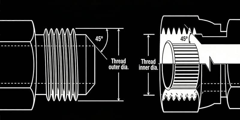
"SAE 45°" indicates an SAE standard connector with a sealing face angle of 45 degrees. These connectors are commonly used in hydraulic systems of automotive and industrial vehicles, especially in low-pressure applications such as fuel and refrigeration systems. They are matched with 45° tapered internal threads and are often used with soft copper tubing, which is easily machined to a 45° angle. Both halves have a 45° flare seat, and the threads of each connector engage together to form a tight mechanical connection, with the seal forming on the 45° flare seat. SAE 45° tapered external threads can only be matched with SAE 45° tapered internal threads, and both have a 45° tapered seat surface, ensuring an effective seal at the 45° tapered seat surface. SAE 45° Flare connectors are identical to JIC 37° Flare connectors, except for the angles of the seats.
| Inch size | Tamaño del guión | Tamaño de la rosca | Male Thread O.D. (in) | Female thread O.D (in) | ||
| 1⁄8 | -2 | 5⁄16 - 24 | 5⁄16 | 0.31 | 9⁄32 | 0.27 |
| 3⁄16 | -3 | 3⁄8 - 24 | 3⁄8 | 0.38 | 11⁄32 | 0.34 |
| 1⁄4 | -4 | 7⁄16 - 20 | 7⁄16 | 0.44 | 13⁄32 | 0.39 |
| 5⁄16 | -5 | 1⁄2 - 20 | 1⁄2 | 0.5 | 15⁄32 | 0.45 |
| 3⁄8 | -6 | 5⁄8 - 18 | 5⁄8 | 0.63 | 9⁄16 | 0.57 |
| 1⁄2 | -8 | 3⁄4 - 16 | 3⁄4 | 0.75 | 11⁄16 | 0.69 |
| 5⁄8 | -10 | 7⁄8 - 14 | 7⁄8 | 0.88 | 13⁄16 | 0.81 |
| 3⁄4 | -12 | 1 1⁄16 - 14 | 11⁄16 | 1.06 | 1 | 0.99 |
| 7⁄8 | -14 | 1 1⁄4 - 12 | 1 1⁄4 | 1.25 | 1 5⁄32 | 1.16 |
| 1 | -16 | 1 3⁄8 - 12 | 1 3⁄8 | 1.38 | 1 9⁄32 | 1.29 |
SAE J1926-1 and ISO 11296-1 - SAE Straight Thread O-ring (O-Ring Boss)
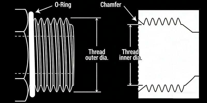
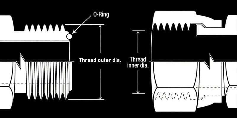
SAE J1926 is a hydraulic quick-connect coupling standard developed by the Society of Automotive Engineers (SAE), specifically designed for high-pressure hydraulic systems in construction machinery, agricultural equipment, and other applications. It uses a 1-1/4"-12 UNF-2A thread (SAE J1926-1 type) and can operate at a maximum pressure of 35 MPa. The female port of the O-Ring Boss has a sealing face, chamfer, and a straight thread. The male connector has an O-ring and a straight thread. The seal is formed when the O-ring is squeezed into the chamfer. The male and female threads bind together to create a mechanically strong connection. This connection is common in high-pressure hydraulic systems.
| Inch size | Tamaño del guión | Tamaño de la rosca | Male Thread O.D. (in) | Female thread O.D (in) | ||
| 1⁄8 | -2 | 5⁄16 - 24 | 5⁄16 | 0.31 | 9⁄32 | 0.27 |
| 3⁄16 | -3 | 3⁄8 - 24 | 3⁄8 | 0.38 | 11⁄32 | 0.34 |
| 1⁄4 | -4 | 7⁄16 - 20 | 7⁄16 | 0.44 | 13⁄32 | 0.39 |
| 5⁄16 | -5 | 1⁄2 - 20 | 1⁄2 | 0.5 | 15⁄32 | 0.45 |
| 3⁄8 | -6 | 9⁄16 - 18 | 9⁄16 | 0.56 | 17⁄32 | 0.51 |
| 1⁄2 | -8 | 3⁄4 - 16 | 3⁄4 | 0.75 | 11⁄16 | 0.69 |
| 5⁄8 | -10 | 7⁄8 - 14 | 7⁄8 | 0.88 | 13⁄16 | 0.81 |
| 3⁄4 | -12 | 1 1⁄16 - 12 | 1 1⁄16 | 1.06 | 1 | 0.98 |
| 7⁄8 | -14 | 1 3⁄16 - 12 | 1 3⁄16 | 1.19 | 1 1⁄8 | 1.1 |
| 1 | -16 | 1 5⁄16 - 12 | 1 5⁄16 | 1.31 | 1 1⁄4 | 1.23 |
| 1 1⁄4 | -20 | 1 5⁄8 - 12 | 1 5⁄8 | 1.63 | 1 9⁄16 | 1.54 |
| 1 1⁄2 | -24 | 1 7⁄8 - 12 | 1 7⁄8 | 1.88 | 1 13⁄16 | 1.79 |
| 2 | -32 | 2 1⁄2 - 12 | 2 1⁄2 | 2.5 | 2 7⁄16 | 2.42 |
O-Ring Face Seal (SAE J1453)
An O-ring face seal is a widely used pipe end connection method. Due to its excellent sealing performance, this connection method is becoming increasingly common. Like the 37° flared fitting, the O-ring face seal (ORFS) fitting is also a three-piece fitting. The thread on the fitting body is a UN/UNF straight thread, which provides tightening force; a groove is machined on the end face to accommodate the O-ring, and a seal is achieved through compression between the O-ring and the other end face. This connection is designed for leak-free use up to 6000 PSI. The O-ring in the face of the straight-thread male end seals against the flat-face female seat and is mechanically held in place by a swivel nut. The female half has a machined flat surface with a straight thread. A seal is achieved when the O-ring on the male end is squeezed onto the female flat-surface seat. The swivel nut on the female half holds the connection together.
SAE Inverted Flare (SAE J512)
The 45° flared (SAE J512) connection type is very common in the refrigeration, automotive, and trucking industries. It consists of two parts: a connector body and a nut. The material is typically brass. The threads of this connector only provide tightening force; the seal is achieved through the contact between the female and male connectors at a 45° taper angle. The SAE J512 45° connection is commonly used in automotive, refrigeration, and truck piping systems and is typically made of brass. Both the external and internal threaded ends have 45° sealing tapers; a seal is achieved through the compression of the internal and external tapers during connection. This connection is also considered a mechanical connection.
SAE J512 chamfered connections are commonly used in automotive systems. This connection uses two types of external threaded ends: a 45° external taper for connecting pipes and a 42° internal taper for connecting other fittings. The internal threaded end has a straight internal thread and a 42° external taper at the bottom. The fitting forms a seal at the point where the internal and external tapers meet. This type of threaded connection is also a mechanical connection.
| Inch size | Tamaño del guión | Tamaño de la rosca | Male Thread O.D. (in) | Female thread O.D (in) | ||
| 1⁄8 | -2 | 5⁄16 - 28 | 5⁄16 | 0.31 | 9⁄32 | 0.27 |
| 3⁄16 | -3 | 3⁄8 - 24 | 3⁄8 | 0.38 | 11⁄32 | 0.34 |
| 1⁄4 | -4 | 7⁄16 - 24 | 7⁄16 | 0.44 | 13⁄32 | 0.39 |
| 5⁄16 | -5 | 1⁄2 - 20 | 1⁄2 | 0.5 | 15⁄32 | 0.45 |
| 3⁄8 | -6 | 5⁄8 - 18 | 5⁄8 | 0.63 | 9⁄16 | 0.57 |
| 7⁄16 | -7 | 11⁄16 - 18 | 11⁄16 | 0.69 | 5⁄8 | 0.63 |
| 1⁄2 | -8 | 3⁄4 - 18 | 3⁄4 | 0.75 | 23⁄32 | 0.7 |
| 5⁄8 | -10 | 7⁄8 - 18 | 7⁄8 | 0.88 | 13⁄16 | 0.81 |
| 3⁄4 | -12 | 1 1⁄16 - 16 | 1 1⁄16 | 1.06 | 1 | 1 |
Four-Bolt Flange (SAE J518 and ISO 6162)
SAE flange standard J518 is a standard for blind flanges, and its design principles conform to SAE J518/ISO 6162 standards. These blind flanges are mainly installed in hydraulic applications, primarily to block passive piping or nozzles in the system. This is the most commonly used standard in North America, and it comes in two pressure rating types: Code 61: working pressure approximately 3000 psi (21 MPa), and Code 62: working pressure up to 6000 psi (42 MPa). It is characterized by imperial units and inch-based hole spacing, and is widely used in the United States, Canada, and parts of the Latin American market. Commonly found in fluid power systems, the Four-Bolt Flange works well connecting 1/2" to 3" hoses and tubes. The seal forms between the O-ring on the male half and the smooth face of the female port (with the O-ring seating on the ring groove of the male). Two clamp halves, held by four bolts, hold the connection together.
| Inch size | Tamaño del guión | Code 61 Bolt Spacing | Code 61 Flange O.D. | Code 62 Bolt Spacing | Code 62 Flange O.D. |
| 1⁄2 | -8 | 1 1⁄2 | 1 3⁄16 | 1 19⁄32 | 1 1⁄4 |
| 3⁄4 | -12 | 1 7⁄8 | 1 1⁄2 | 2 | 1 5⁄8 |
| 1 | -16 | 2 1⁄16 | 1 3⁄4 | 2 1⁄4 | 1 7⁄8 |
| 1 1⁄4 | -20 | 2 5⁄16 | 2 | 2 5⁄8 | 2 1⁄8 |
| 1 1⁄2 | -24 | 2 3⁄4 | 2 3⁄8 | 3 1⁄8 | 2 1⁄2 |
| 2 | -32 | 3 1⁄16 | 2 13⁄32 | 3 13⁄16 | 3 1⁄8 |
| 2 1⁄2 | -40 | 3 1⁄2 | 3 5⁄16 | n/a | n/a |
| 3 | -48 | 4 3⁄16 | 4 | n/a | n/a |
O Ring Pilot Threads
This connection is widely found in automotive and commercial air conditioning applications. Both male and female halves have a pilot (could be long or short), and the seal is made when the O-ring is compressed. Threads tightly mesh together to form a strong mechanical bond.
| Inch size | Tamaño del guión | Rosca macho | Female thread | ||
| Thread size | Thread O.D. | Thread size | Thread I.D. | ||
| 3⁄8 | -6 | 5⁄8 - 18 | 5⁄8 | 5⁄8 - 18 | 9⁄16 |
| 1⁄2 | -8 | 3⁄4 - 18 | 3⁄4 | 3⁄4 - 16 | 11⁄16 |
| 5⁄8 | -10 | 7⁄8 - 18 | 7⁄8 | 7⁄8 - 14 | 13⁄16 |
| 3⁄4 | -12 | 1 1⁄16 - 16 | 1 1⁄16 | 1 1⁄16 - 14 | 1 |
BSP - British Connections
British Standard Pipe (BSP) is a set of technical standards for screw threads that has been adopted internationally for interconnecting and sealing pipes and fittings by mating an external (male) thread with an internal (female) thread. It has been adopted as a standard in plumbing and pipe fitting, except in North America. Two types of threads are distinguished: BSPP (British Standard Pipe Thread) and BSPT (55-degree tapered pipe thread). It is worth noting that BSPT is not compatible with the American Standard 60-degree tapered pipe thread (NPT); the two are significantly different.
British Standard Pipe Parallel (BSPP)
BSPP (British Standard Pipe Parallel) is a British standard thread, also known as a parallel pipe thread. It is a common threaded connection standard widely used in hydraulic systems, pipe connections, and other industrial equipment. BSPP thread standards are widely used in hydraulic systems and pipe connections. In hydraulic systems, BSPP threaded connections are commonly used to connect hydraulic pumps, valves, cylinders, and other hydraulic components. Its sealing performance and reliability make it a common connection method in hydraulic systems. Furthermore, the BSPP thread standard is also widely used in pipe connections of industrial equipment and machinery to ensure the strength and sealing of pipe connections.
| Inch size | Tamaño del guión | Tamaño de la rosca | Male Thread O.D. (in) | Female thread O.D (in) | ||
| 1⁄8 | -2 | 1⁄8 - 28 | 3⁄8 | 0.38 | 11⁄32 | 0.35 |
| 1⁄4 | -4 | 1⁄4 - 19 | 33⁄64 | 0.52 | 15⁄32 | 0.47 |
| 3⁄8 | -6 | 3⁄8 - 19 | 21⁄32 | 0.65 | 19⁄32 | 0.6 |
| 1⁄2 | -8 | 1⁄2 - 14 | 13⁄16 | 0.82 | 3⁄4 | 0.75 |
| 5⁄8 | -10 | 5⁄8 - 14 | 7⁄8 | 0.88 | 13⁄16 | 0.8 |
| 3⁄4 | -12 | 3⁄4 - 14 | 1 1⁄32 | 1.04 | 31⁄32 | 0.97 |
| 1 | -16 | 1 - 11 | 1 5⁄16 | 1.3 | 1 7⁄32 | 1.22 |
| 1 1⁄4 | -20 | 1 1⁄4 - 11 | 1 21⁄32 | 1.65 | 1 9⁄16 | 1.56 |
| 1 1⁄2 | -24 | 1 1⁄2 - 11 | 1 7⁄8 | 1.88 | 1 25⁄32 | 1.79 |
| 2 | -32 | 2 - 11 | 2 11⁄32 | 2.35 | 2 1⁄4 | 2.26 |
British Standard Pipe Tapered (BSPT)
BSPT is primarily used in Europe and the UK, and also in other applications requiring tapered thread connections. The tapered male connects with a tapered female, with the seal forming in the threads. This type of thread is mainly used for pipe connections and the connection of mechanical components. It is widely used in the oil, chemical, and natural gas industries. Although the BSPT male end is comparable to the National Pipe Tapered Fuel (NPTF), they are not interchangeable due to their different sizes and thread forms.
| Inch size | Tamaño del guión | Tamaño de la rosca | Male Thread O.D. (in) | Female thread O.D (in) | ||
| 1⁄8 | -2 | 1⁄8 - 28 | 3⁄8 | 0.38 | 11⁄32 | 0.35 |
| 1⁄4 | -4 | 1⁄4 - 19 | 33⁄64 | 0.52 | 15⁄32 | 0.47 |
| 3⁄8 | -6 | 3⁄8 - 19 | 21⁄32 | 0.65 | 19⁄32 | 0.6 |
| 1⁄2 | -8 | 1⁄2 - 14 | 13⁄16 | 0.82 | 3⁄4 | 0.75 |
| 5⁄8 | -10 | 5⁄8 - 14 | 7⁄8 | 0.88 | 13⁄16 | 0.8 |
| 3⁄4 | -12 | 3⁄4 - 14 | 1 1⁄32 | 1.04 | 31⁄32 | 0.97 |
| 1 | -16 | 1 - 11 | 1 5⁄16 | 1.3 | 1 7⁄32 | 1.22 |
| 1 1⁄4 | -20 | 1 1⁄4 - 11 | 1 21⁄32 | 1.65 | 1 9⁄16 | 1.56 |
| 1 1⁄2 | -24 | 1 1⁄2 - 11 | 1 7⁄8 | 1.88 | 1 25⁄32 | 1.79 |
| 2 | -32 | 2 - 11 | 2 11⁄32 | 2.35 | 2 1⁄4 | 2.26 |
ISO connection
ISO 261 Threads & O-ring Seal
The male half has an O-ring and a straight thread, while the female half has a machined surface, a chamfer, and a straight thread. The O-ring on the male half compresses the chamfer of the female port to form a seal. ISO 6149-2 includes two types of threads: triangular threads and rectangular threads. Triangular threads are mainly used for general connections, fastening, and adjustment; rectangular threads are used for connections that withstand axial forces and have higher load-bearing capacity. ISO 6149-2 provides detailed specifications and requirements for the design, production, and inspection of threaded connections in the aerospace, automotive, and other fields. (ISO 6149 is the same as the SAE J1926-1 O-ring Boss, except that ISO 6149 includes metric threads.) The straight threads mesh to form a strong mechanical bond.
| Metric Thread Size | Male Thread O.D. (mm) | Female Thread I.D (mm) |
| M8 x 1.0 | 8 | 7 |
| M10 x 1.0 | 10 | 9 |
| M12 x 1.5 | 12 | 10.5 |
| M14 x 1.5 | 14 | 12.5 |
| M16 x 1.5 | 16 | 14.5 |
| M18 x 1.5 | 18 | 16.5 |
| M22 x 1.5 | 22 | 20.5 |
| M27 x 2.0 | 27 | 25 |
| M33 x 2.0 | 33 | 31 |
| M42 x 2.0 | 42 | 40 |
| M48 x 2.0 | 48 | 46 |
| M60 x 2.0 | 60 | 58 |
DIN connection
DIN 7631
DIN 7631 is a technical standard developed by the German National Organization for Standardization (BNU) to specify the design, dimensions, and material requirements for hose fittings used in hydraulic systems. DIN 7631 applies to hose fittings in hydraulic piping systems. These fittings are primarily used to transfer hydraulic fluids and ensure the system's sealing and safety. The standard specifies the performance and technical specifications that hose fittings should possess to ensure their suitability for applications in various industrial sectors.
| Pipe/Tube O.D. (mm) | Metric Thread Size | Male Thread O.D. (mm) | Female Thread I.D (mm) |
| 6 | M12 x 1.5 | 12 | 10.5 |
| 8 | M14 x 1.5 | 14 | 12.5 |
| 10 | M16 x 1.5 | 16 | 14.5 |
| 12 | M18 x 1.5 | 18 | 16.5 |
| 15 | M22 x 1.5 | 22 | 20.5 |
| 18 | M26 x 1.5 | 26 | 24.5 |
| 22 | M30 x 1.5 | 30 | 28.5 |
| 28 | M38 x 1.5 | 38 | 36.5 |
| 35 | M45 x 1.5 | 45 | 43.5 |
| 52 | M52 x 1.5 | 52 | 50.5 |
DIN 2353 24° Cone
DIN 2353 compression fittings are standardized connectors used in hydraulic systems to establish leak-proof connections between pipes, tubing, and hoses. These fittings conform to the German standard DIN 2353, which specifies the design, dimensions, and performance requirements for metric compression fittings. They consist of three main components: a body, a cut-off ring, and a nut. A ferrule is placed between the body and the nut, deforming when the nut is tightened to form a secure and reliable connection that can withstand high pressure and vibration. DIN 2353 compression fittings are widely used in hydraulic systems in industries such as automotive, manufacturing, and machinery, where robust and efficient fluid connections are crucial.
| DIN 2353 L Tube O.D.(mm) | DIN 2353 S Tube O.D. (mm) | Metric Thread Size | Male Thread O.D. (mm) | Female Thread I.D (mm) |
| 6 | M12 x 1.5 | 12 | 10.5 | |
| 8 | 6 | M14 x 1.5 | 14 | 12.5 |
| 10 | 8 | M16 x 1.5 | 16 | 14.5 |
| 12 | 10 | M18 x 1.5 | 18 | 16.5 |
| 12 | M20 x 1.5 | 20 | 18.5 | |
| 15 | 14 | M22 x 1.5 | 22 | 20.5 |
| 16 | M24 x 1.5 | 24 | 22.5 | |
| 18 | M26 x 1.5 | 26 | 24.5 | |
| 22 | 20 | M30 x 2.0 | 30 | 28 |
| 28 | 25 | M36 x 2.0 | 36 | 34 |
| 30 | M42 x 2.0 | 42 | 40 | |
| 35 | M45 x 2.0 | 45 | 43 | |
| 42 | 38 | M52 x 2.0 | 52 | 50 |
JIS connection
Japanese Industrial Standard (JIS) threads embody the meticulous craftsmanship of Japanese manufacturing. The JIS standard emphasizes consistency of quality and precision in production, and is highly regarded in the international market.
Japanese Industrial Standard JIS 300 Flare
| Inch size | Tamaño del guión | Tamaño de la rosca | Male Thread O.D. (in) | Female thread O.D (in) | ||
| 1⁄8 | -2 | 1⁄8 - 28 | 3⁄8 | 0.38 | 11⁄32 | 0.35 |
| 1⁄4 | -4 | 1⁄4 - 19 | 33⁄64 | 0.52 | 15⁄32 | 0.47 |
| 3⁄8 | -6 | 3⁄8 - 19 | 21⁄32 | 0.65 | 19⁄32 | 0.6 |
| 1⁄2 | -8 | 1⁄2 - 14 | 13⁄16 | 0.82 | 3⁄4 | 0.75 |
| 5⁄8 | -10 | 5⁄8 - 14 | 7⁄8 | 0.88 | 13⁄16 | 0.8 |
| 3⁄4 | -12 | 3⁄4 - 14 | 1 1⁄32 | 1.04 | 31⁄32 | 0.97 |
| 1 | -16 | 1 - 11 | 1 5⁄16 | 1.3 | 1 7⁄32 | 1.22 |
| 1 1⁄4 | -20 | 1 1⁄4 - 11 | 1 21⁄32 | 1.65 | 1 9⁄16 | 1.56 |
| 1 1⁄2 | -24 | 1 1⁄2 - 11 | 1 7⁄8 | 1.88 | 1 25⁄32 | 1.79 |
| 2 | -32 | 2 - 11 | 2 11⁄32 | 2.35 | 2 1⁄4 | 2.26 |
Komatsu 30° Flare (JIS Metric)
| Tamaño del tablero | Metric Thread Size | Male Thread O.D. (mm) | Female Thread I.D (mm) |
| -6 | M18 x 1.5 | 18 | 16.5 |
| -8 | M22 x 1.5 | 22 | 20.5 |
| -10 | M24 x 1.5 | 24 | 22.5 |
| -12 | M30 x 1.5 | 30 | 28.5 |
| -16 | M33 x 1.5 | 33 | 31.5 |
| -20 | M36 x 1.5 | 36 | 34.5 |
| -24 | M42 x 1.5 | 42 | 40.5 |